Structured cabling is the physical infrastructure that enables devices and systems within a building to communicate. It connects workstations, IP phones, Wi-Fi access points, cameras, printers, network equipment, telecommunications rooms, and server rooms.
The ANSI/TIA-568 series of standards, published by the Telecommunications Industry Association, provides a framework for planning and implementing structured cabling systems. These standards address telecommunications spaces, network topology, distances, components, installation practices, performance requirements, and testing.
In simple terms, structured cabling is an organized way to build a building’s physical network. Instead of adding cables randomly as needs arise, it creates a clear, documented architecture that can evolve with the organization.
The word “structured” means that the system is not improvised.
In an unstructured installation, cables are often added one by one based on urgent needs or immediate requirements. This may work in the short term. Over time, however, the infrastructure becomes difficult to understand, modify and troubleshoot.
In a structured infrastructure, cables are grouped, terminated, identified and documented according to a planned logic. Links return to organized termination points, such as patch panels in a telecom room. Cable pathways are planned. Outlets are identified. Testing and documentation make it possible to know what was installed and where each link terminates.
The goal is not only to connect devices today. The goal is to create an infrastructure that can support future changes: new workstations, office moves, Wi-Fi access points, cameras, connected equipment, server rooms and network upgrades.
Poorly planned physical infrastructure can cause several issues:
A well-designed infrastructure, on the other hand, supports daily operations and future needs. It helps an organization plan for additional workstations, Wi-Fi access points, cameras, connected equipment, server rooms and interconnections between buildings.
A structured cabling system is generally organized around several areas. This organization makes it possible to distribute the network throughout a building without creating a buildup of unplanned cable runs.
Entrance Facility
The entrance facility is the point where external services enter the building, such as Internet, telecom or fiber links from a service provider.
Equipment Room or MDF
The equipment room houses the main network equipment. In many projects, this area is also referred to as the MDF, or Main Distribution Frame. It is often the central point where external services arrive and where key equipment is installed, such as routers, firewalls, core switches and patch panels.
The MDF must be carefully planned, since a problem in this area can affect a large part of the network, or even the entire network.
Telecom Rooms or IDFs
Telecom rooms serve as local distribution points. In common network project terminology, they are often referred to as IDFs, or Intermediate Distribution Frames. An IDF can serve a floor, wing, department or specific area of a building.
The goal is to bring network distribution closer to users and equipment. This helps limit horizontal cable lengths, simplify maintenance and troubleshooting, and organize the infrastructure by area..
Backbone
The backbone is the physical link that connects the MDF to the IDFs, or connects multiple rooms, floors, server rooms or buildings together. It acts as the spine of the network.
In many environments, the backbone is built with fiber optic cabling to support longer distances, higher bandwidth and future growth.
Horizontal Cabling
Horizontal cabling connects telecom rooms or IDFs to network outlets in work areas. It serves offices, meeting rooms, Wi-Fi access points, cameras, printers and other connected equipment.
Work Area
The work area refers to the spaces where users and equipment connect to the network: offices, workstations, conference rooms, common areas, warehouses or technical spaces.
This hierarchy makes the infrastructure easier to read, easier to expand and easier to troubleshoot. It also helps isolate issues more quickly: an incident in an IDF may affect a specific area, while a problem in the MDF can have a much broader impact.
A structured cabling system is made up of several physical components. These components must be properly selected, installed, identified and tested to ensure the reliability of the infrastructure.
Network Cables
Network cables form the physical links between work areas, telecom rooms and network equipment. In commercial environments, copper cabling such as Cat6 or Cat6A is often used for network outlets, workstations, IP phones, cameras and Wi-Fi access points.
Fiber optic cabling is typically used for backbone links, interconnections between rooms, links between buildings or environments that require more capacity or longer distances.
Connectors and Network Outlets
Connectors and network outlets are the points where equipment connects to the infrastructure. They are found in offices, meeting rooms, common areas, warehouses, technical rooms and other work areas.
Their placement must be planned according to the real needs of the building: user workstations, printers, IP phones, cameras, Wi-Fi access points, specialized equipment and future requirements.
Patch Panels
Patch panels are used to terminate and organize cables inside racks or network cabinets. Each patch panel port normally corresponds to an identified outlet or link in the building.
They make it possible to modify connections cleanly without directly manipulating the permanent cabling. Proper patch panel identification also simplifies troubleshooting, additions and changes.
Patch Cords
Patch cords connect patch panels to active equipment, such as network switches. They are also used to connect devices to network outlets in work areas.
Although they may seem secondary, patch cords must be appropriate for the installation, properly organized and replaced when damaged or poorly sized.
Racks and Network Cabinets
Racks and cabinets are used to group patch panels, switches, network equipment, cable managers and distribution accessories.
A well-organized rack improves equipment access, airflow, security, maintenance, and the overall clarity of the installation.
Cable Pathways
Cable pathways, conduits, trays, raceways and supports are used to route cables safely and in an organized way throughout the building.
They must be planned to protect the cables, respect site constraints, maintain proper organization and allow for future growth.
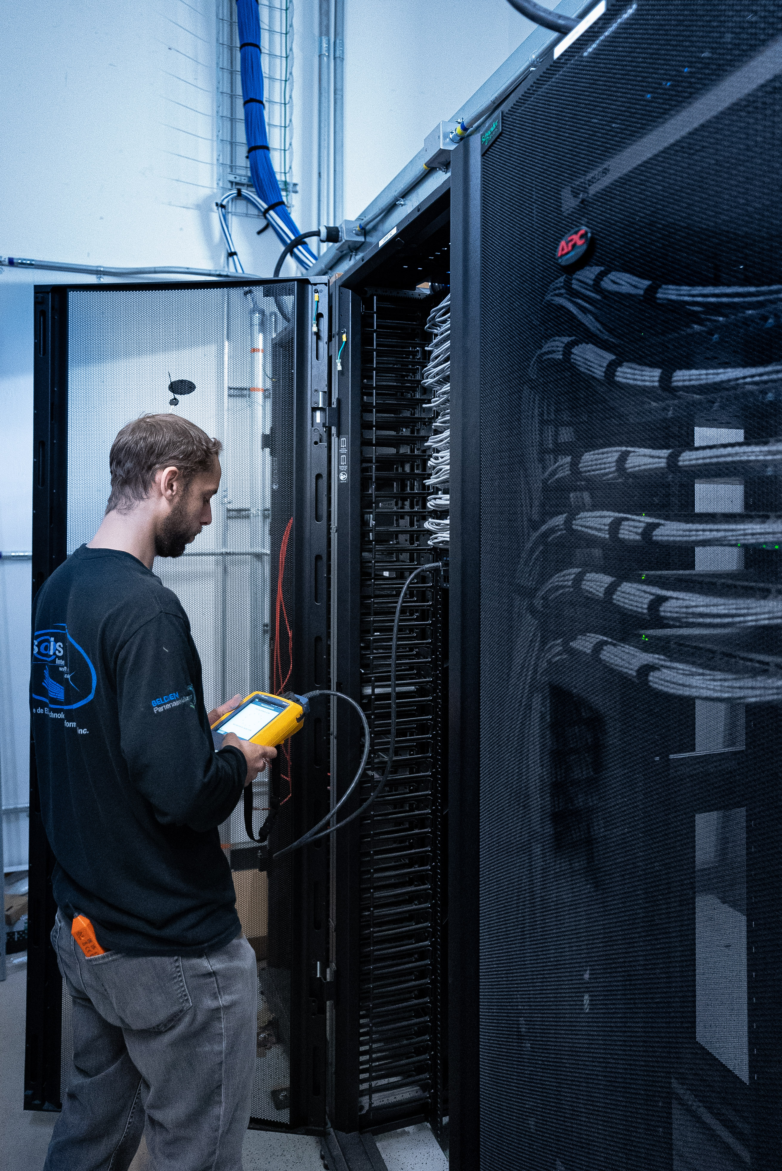
A professional structured cabling installation does not stop at cable installation. Links must also be tested, identified and documented.
Certification confirms that the installed links meet the expected performance requirements.
Labeling identifies each link at both ends.
Documentation makes it possible to know where each cable starts, where it ends and how it is used.
Clear documentation may include:
For an IT manager, building manager or project manager, this documentation reduces risk and speeds up future service interventions.
A business should consider a cabling assessment if it is experiencing:
In these situations, the physical infrastructure can become a bottleneck if it is not designed around the actual needs of the site.
During a project, SAIS assesses the site’s requirements, available pathways, telecommunications rooms, distances, and required cable types. Our structured cabling services also include terminations, labeling, certification, and final documentation.
The goal is to deliver a clean, reliable, secure, and maintainable infrastructure designed around the building’s current requirements and future growth.
No. Even a small or mid-sized office can benefit from structured cabling. The clearer the infrastructure is from the start, the easier additions and changes become.
No. Wi-Fi depends on cabling. Wi-Fi access points must be connected to the physical network to transmit data and, in many cases, receive power through PoE.
Certification confirms that the installed links meet the expected performance requirements. It also documents the quality of the installation and reduces uncertainty when troubleshooting network issues.
Planning a structured cabling, fiber-optic, or server room project? Explore our cabling infrastructure solutions or contact SAIS Interconnexion to determine the right approach for your site.